Stay in touch to keep up with the latest on EJF's newest developments!
First Flight
">
Maneuvering Capability Test
Wednesday, February 10, 2010
Tuesday, February 2, 2010


Wednesday, April 8, 2009
More on Ductwork at EJF.com
For an in depth reading of airflow physics goto http://en.wikipedia.org/wiki/Fluid_dynamics
For the benefit of my EJF customers I will stay focused on the real meat and potatoes of EDF Jets with examples. I have spent over 10 years convert many Turbine and fuelled EDFs to Electric including 1.8 scale machine with 12ils thrust for a 12lb craft. I'm not trying to taunt the Physics Police and get pulled over, just present some working solutions. I do enjoy the e-mail so keep it going and be specific. Review the past document lists in previous EDF columns for references.
The 10 Cent Tailpipe

Let's start with the tail and work forward, The tailpipe can be derived from some very common items. I'll be using the Mini Fan and HET 6904 series of EDF units however this technique will work for others. Notice in Figure 1. that these look like ordinary plastic cups. Well yes they are, the 16 oz. and 32 oz. Solo cup once cut to size make a perfect tailpipe that can then be painted and detailed.
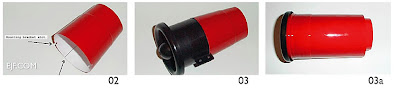 The Mini Fan has a 72 mm outside diameter so to better adjust both the coupling of the tailpipe to the EDF unit and adjust the exhaust diameter of the tailpipe a lengthwise cut is required for proper adjustment. Once the position is in place C.A. can be applied for a permanent seam. Figure 3. shows the tailpipe connected to the Mini Fan and Figure 3a. shows how you can use the 32 oz. cup to make a complete nacelle. When the tailpipe is ready for connection it's advisable to tack it into place with C.A. and then use a thickened bead of epoxy around the circumference. Don't try to do both sides at once, unless you're in micro gravity that is.
 The HET 6904 series of EDF units and Pro both have a 70 mm outside diameter and I wasn't required to make a lengthwise cut as you will see. Notice in Figure 4. the cut locations and the resulting Figure 4a. Once each is cut the tailpipe now has a flange that makes a very nice coupled joint at the EDF unit and a clean exhaust path for the air. Figure 5. shows the attached tailpipe ready for action.
The Mighty Ducts
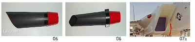 Don't worry these are not shots of my shop vac attachment just so we get that out of the way, This is one side of my twin F-15 intake duct form, Also known as a cheek inlet. Figure 7a. shows what the full scale F-15 intake looks like. Notice the side view in Figure 6. I have included a similar angle as part of the ducting. Also notice the bottom view in Figure 7. do you notice that there is a shape change? By now you may realize that this duct is made from the standard intake duct size as it couples to the EDF unit. The intake lips are actually part of the fuselage not shown.
Now this takes us into the next important issue of duct design, maintaining the volume of air that the EDF unit receives. Just as we see different shapes and sizes of drinking cups that hold the same amount of liquid, We also have different shapes in ducting that are required to keep the same volume of air despite their shape. I've chosen to use a standard duct size and alter the intake area by forming the intake to the desired shape.
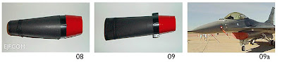 Figure 8. shows the intake duct for a F-16 chin inlet and Figure 9. shows that the shape has been alliterated however the volume has been maintained. Again here is the full scale F-16's intake Figure 9a. notice the shape. Also note that the intake lip is part of the fuselage not shown.
What is it?
Animal, Vegetable or Mineral? Don't worry it's not organic, This is a duct system for a wet jet F-117 that uses a single 5" fan unit. Many of the scale wet jets use a single ducted fan unit for both reliability and cost sa vings. Over the years many manufactures have become very creative in making bifurcated inlets and outlets and this is a whopper. As we have discussed maintaining the air volume is alive and well in this design. When using a bifurcated system the total area of each side must create the required air volume as well as the tailpipe totals.
This is a duct system for a wet jet F/A-18 that uses a single 5" fan unit. I coupled the two ends together just for effect. Where the two pieces are joined is where the fan unit would set.
 Here is a sneak peek at one of my EDF test stands where I've spent over a month with cell counts and ducting experiments that has left me speechless with glee!
Summary
I hope by now your feeling of EDF design is less intimidating than when we first started, There are many complex topics involved and I hope I haven't watered them down to much so useful work can be done. After all we want to fly Jet like model aircraft, that's why your reading this.
For the benefit of my EJF customers I will stay focused on the real meat and potatoes of EDF Jets with examples. I have spent over 10 years convert many Turbine and fuelled EDFs to Electric including 1.8 scale machine with 12ils thrust for a 12lb craft. I'm not trying to taunt the Physics Police and get pulled over, just present some working solutions. I do enjoy the e-mail so keep it going and be specific. Review the past document lists in previous EDF columns for references.
The 10 Cent Tailpipe

Let's start with the tail and work forward, The tailpipe can be derived from some very common items. I'll be using the Mini Fan and HET 6904 series of EDF units however this technique will work for others. Notice in Figure 1. that these look like ordinary plastic cups. Well yes they are, the 16 oz. and 32 oz. Solo cup once cut to size make a perfect tailpipe that can then be painted and detailed.
 The Mini Fan has a 72 mm outside diameter so to better adjust both the coupling of the tailpipe to the EDF unit and adjust the exhaust diameter of the tailpipe a lengthwise cut is required for proper adjustment. Once the position is in place C.A. can be applied for a permanent seam. Figure 3. shows the tailpipe connected to the Mini Fan and Figure 3a. shows how you can use the 32 oz. cup to make a complete nacelle. When the tailpipe is ready for connection it's advisable to tack it into place with C.A. and then use a thickened bead of epoxy around the circumference. Don't try to do both sides at once, unless you're in micro gravity that is.
 The HET 6904 series of EDF units and Pro both have a 70 mm outside diameter and I wasn't required to make a lengthwise cut as you will see. Notice in Figure 4. the cut locations and the resulting Figure 4a. Once each is cut the tailpipe now has a flange that makes a very nice coupled joint at the EDF unit and a clean exhaust path for the air. Figure 5. shows the attached tailpipe ready for action.
The Mighty Ducts
 Don't worry these are not shots of my shop vac attachment just so we get that out of the way, This is one side of my twin F-15 intake duct form, Also known as a cheek inlet. Figure 7a. shows what the full scale F-15 intake looks like. Notice the side view in Figure 6. I have included a similar angle as part of the ducting. Also notice the bottom view in Figure 7. do you notice that there is a shape change? By now you may realize that this duct is made from the standard intake duct size as it couples to the EDF unit. The intake lips are actually part of the fuselage not shown.
Now this takes us into the next important issue of duct design, maintaining the volume of air that the EDF unit receives. Just as we see different shapes and sizes of drinking cups that hold the same amount of liquid, We also have different shapes in ducting that are required to keep the same volume of air despite their shape. I've chosen to use a standard duct size and alter the intake area by forming the intake to the desired shape.
 Figure 8. shows the intake duct for a F-16 chin inlet and Figure 9. shows that the shape has been alliterated however the volume has been maintained. Again here is the full scale F-16's intake Figure 9a. notice the shape. Also note that the intake lip is part of the fuselage not shown.
What is it?

Animal, Vegetable or Mineral? Don't worry it's not organic, This is a duct system for a wet jet F-117 that uses a single 5" fan unit. Many of the scale wet jets use a single ducted fan unit for both reliability and cost sa
 vings. Over the years many manufactures have become very creative in making bifurcated inlets and outlets and this is a whopper. As we have discussed maintaining the air volume is alive and well in this design. When using a bifurcated system the total area of each side must create the required air volume as well as the tailpipe totals.
This is a duct system for a wet jet F/A-18 that uses a single 5" fan unit. I coupled the two ends together just for effect. Where the two pieces are joined is where the fan unit would set.
 Here is a sneak peek at one of my EDF test stands where I've spent over a month with cell counts and ducting experiments that has left me speechless with glee!
Summary
I hope by now your feeling of EDF design is less intimidating than when we first started, There are many complex topics involved and I hope I haven't watered them down to much so useful work can be done. After all we want to fly Jet like model aircraft, that's why your reading this.
- 1. Keep the volume of air through the intake matched to the EDF unit despite the shape.
- 2. Keep the inside exhaust diameter of the tailpipe to around 90% of the impeller diameter.
- 3. Keep the inlet and outlet connections to the EDF unit as air tight as possible.
Tuesday, April 7, 2009
Bungee Launching an EDF Jet
I know, your first thought is add some retractable gear and voila. Well there are a couple of problems with that. The first problem is the added weight and the second is steering the aircraft while it's accelerating. Enter the EJF bungee Launcher - 10 years in the making - looks like this
Bungee launching is particularly suited to FAST jets with low weight and narrow airfoil sections like the HET series electric jets because it takes them safely past stall speed with a repeatable trajectory. The guide rails make sure there is no interference in roll and the pitch angle is positive.
Question : Bungee or Hand Launch?
How do I reliably get my electric jet in the air since it doesn't have any landing gear to speak of? To prepare for my excursion in this area I used two of my smaller electric jets: the FVK HE-162 using a Mini Fan and a SU-27 Pusher Prop Jet. The most popular methods of launching these kinds of planes are Hand Launching and Bungee Launching (e.g. Surgical tubing. or Hi Start) .
The Hand Launch Horrors
For those of you who haven't experienced this you might think hand launching is the most cost effective and reliable way, and most have a mental picture of gracefully tossing the plane from their hands with a nice gentle altitude gaining departure, and all is happy and fine. Wakeup!!! We're not on the edge of a slope with a 15 to 20 mph constant head wind on our launches! We need airspeed and we need it now! The few people that do try the carefree method will become either very accomplished re-builders or join the 20 second club of pilots. My second tip of the column is: Just don't even think about it.
Yes, all of us who have been doing the one man band method will argue that "nobody else can either fly it or hand launch it as good as myself so that's why I do it". I, too, have been in the same situation and on occasion biff it. The only advice I can give here is you need two people. The pilot and the launcher. Oh, did I forget to mention you need a specific launcher type person? OK, you need to find someone that you trust and who knows how to run reasonably fast and can throw about two pounds in the air at the correct release angle into the wind and not squeeze the servos out of it while do so. Umm, I didn't say it would be easy. Ever think about what would happen if the motor stopped working right after launch or your friends changes his wrist angle? That's right - CRUNCH! Its much better to get the plane airborne with enough speed for safe flight even if the motor isn't working at all. For that we need to rely on a bungee.
Bungee Launching
Before jumping into my adventure I collected as many bungee launching methods as possible and then came up with what I use and enjoy. What I'm going to describe will not be new developments in bungee launching but the specific details of the method I now use to reliably launch my electric jets wherever I go. You will be able to teach most anyone how to do it. As you might gather I suggest two people: the pilot and launcher. The stress factor is much less when you're able to concentrate on the aircraft instead of the gymnastics of launching as well as flying.
One of the myste ries to bungee launching is where does the tow hook mount? For this question I experimented with two different locations. On the HE-162 1" from the tip of the nose and for the SU-27 it was placed 4" in front of the C.G. Both spots worked very well. One of the reasons you don't mount it on or behind the C.G. is that it would go nose up and look like you were launching a kite and probably rip the wings off at the very minimum. Remember, you're trying to get past the stall speed and attain level flight- not launch the aircraft to some desired altitude. For the tow hook I wanted to try something a little different so that I could easily retrofit it on any of
 my existing aircraft. For the HE-162 I used a single medium sized du-bro nylon control horn with the normal either side sandwich mounting method and added some epoxy. On the SU-27 I used the du-bro nylon right/left control horns and CA glued them together and used the normal sandwich mounting method. Both are strong and launch great.
The bungee is comprised of 15' of surgical tubing and 10' of towline, three steel split rings and a steel anchor stake. I found that pacing off 45' to 55' of stretch was fine in my tests. The approximate weight limit is around 45 ounces. I'm sure there are other distances that work however I didn't test them all. It also works out better if you don't have so much stretch on the bungee that the launcher has trouble standing with it. The following technique is very straight forward and has three complete steps.
The Reliable Launch
1. The pilot should retrieve the bungee and verify that the anchor stake is properly set and all split ring connections are sound before each flight. After a couple of times it becomes a natural habit when walking back to the launch area verifying the bungee along the way. The launcher should carry the aircraft like the Bob-E shown here (not a scale jet but much faster than most scale craft in the air) and radio with the switches off and follow the pilot to the launching area. As you reach the launching area it should be clear why the pilot does these steps with the bungee since anything to do with the flight process should be the pilot's responsibility such as direction into the wind and launch placement.
2. The launcher sets the aircraft and radio down and then the pilot hands over the bungee to the launcher holding onto the split ring. The pilot now turns on the radio and then the aircraft and does the pre-flight surface and power tests. The pilot then hands the aircraft to the launcher, it should be the opposite hand to the one holding the split ring. The pilot should move behind the launcher about six feet and to either side 3 feet for visibility.
3. The pilot then verifies just the elevator or ailerons/rudder, applies a small amount of up elevator and announces 'Ready' the launcher then applies the split ring to the towhook and stands up straight with the aircraft over head and then acknowledges with 'Set' and waits for the final command from the pilot which is 'Launch' the launcher then releases the aircraft with a slight pushing forward motion and then stays still or kneels down. The pilot then applies throttle and makes a level accent followed by a slow turn away from the flight line area.
And there you go, I hope you can see that two people cooperating make a nice stress free and predictable launch every time. I'm not saying that potential incidents can't happen like when the launcher has that sudden itch that must be scratched and you almost have a pre-mature launch condition (hopefully with the receiver on). Or, the pilot bumps the throttle startling the launcher. I must say that one of the most interesting launches is my SU-27 with it's pusher prop. This is where the trust factor comes into play between the pilot and launcher (similar to the holder and kicker in football). Since this method instructs that the aircraft i s always clear of the launcher before throttle is applied the Puller, Pusher and EDF are all accommodated. The acceleration effects of the bungee launch are well over the power output of the throttle for the first few seconds anyway.
This leads me to the new EJF Bungee system. Check out the video on this post.
I would also like to say that during the creation of this column no electric jets were hurt or killed. :)
Bungee launching is particularly suited to FAST jets with low weight and narrow airfoil sections like the HET series electric jets because it takes them safely past stall speed with a repeatable trajectory. The guide rails make sure there is no interference in roll and the pitch angle is positive.
Question : Bungee or Hand Launch?
How do I reliably get my electric jet in the air since it doesn't have any landing gear to speak of? To prepare for my excursion in this area I used two of my smaller electric jets: the FVK HE-162 using a Mini Fan and a SU-27 Pusher Prop Jet. The most popular methods of launching these kinds of planes are Hand Launching and Bungee Launching (e.g. Surgical tubing. or Hi Start) .
The Hand Launch Horrors
For those of you who haven't experienced this you might think hand launching is the most cost effective and reliable way, and most have a mental picture of gracefully tossing the plane from their hands with a nice gentle altitude gaining departure, and all is happy and fine. Wakeup!!! We're not on the edge of a slope with a 15 to 20 mph constant head wind on our launches! We need airspeed and we need it now! The few people that do try the carefree method will become either very accomplished re-builders or join the 20 second club of pilots. My second tip of the column is: Just don't even think about it.
Yes, all of us who have been doing the one man band method will argue that "nobody else can either fly it or hand launch it as good as myself so that's why I do it". I, too, have been in the same situation and on occasion biff it. The only advice I can give here is you need two people. The pilot and the launcher. Oh, did I forget to mention you need a specific launcher type person? OK, you need to find someone that you trust and who knows how to run reasonably fast and can throw about two pounds in the air at the correct release angle into the wind and not squeeze the servos out of it while do so. Umm, I didn't say it would be easy. Ever think about what would happen if the motor stopped working right after launch or your friends changes his wrist angle? That's right - CRUNCH! Its much better to get the plane airborne with enough speed for safe flight even if the motor isn't working at all. For that we need to rely on a bungee.
Bungee Launching

Before jumping into my adventure I collected as many bungee launching methods as possible and then came up with what I use and enjoy. What I'm going to describe will not be new developments in bungee launching but the specific details of the method I now use to reliably launch my electric jets wherever I go. You will be able to teach most anyone how to do it. As you might gather I suggest two people: the pilot and launcher. The stress factor is much less when you're able to concentrate on the aircraft instead of the gymnastics of launching as well as flying.
One of the myste
 ries to bungee launching is where does the tow hook mount? For this question I experimented with two different locations. On the HE-162 1" from the tip of the nose and for the SU-27 it was placed 4" in front of the C.G. Both spots worked very well. One of the reasons you don't mount it on or behind the C.G. is that it would go nose up and look like you were launching a kite and probably rip the wings off at the very minimum. Remember, you're trying to get past the stall speed and attain level flight- not launch the aircraft to some desired altitude. For the tow hook I wanted to try something a little different so that I could easily retrofit it on any of
 my existing aircraft. For the HE-162 I used a single medium sized du-bro nylon control horn with the normal either side sandwich mounting method and added some epoxy. On the SU-27 I used the du-bro nylon right/left control horns and CA glued them together and used the normal sandwich mounting method. Both are strong and launch great.
The bungee is comprised of 15' of surgical tubing and 10' of towline, three steel split rings and a steel anchor stake. I found that pacing off 45' to 55' of stretch was fine in my tests. The approximate weight limit is around 45 ounces. I'm sure there are other distances that work however I didn't test them all. It also works out better if you don't have so much stretch on the bungee that the launcher has trouble standing with it. The following technique is very straight forward and has three complete steps.
The Reliable Launch

1. The pilot should retrieve the bungee and verify that the anchor stake is properly set and all split ring connections are sound before each flight. After a couple of times it becomes a natural habit when walking back to the launch area verifying the bungee along the way. The launcher should carry the aircraft like the Bob-E shown here (not a scale jet but much faster than most scale craft in the air) and radio with the switches off and follow the pilot to the launching area. As you reach the launching area it should be clear why the pilot does these steps with the bungee since anything to do with the flight process should be the pilot's responsibility such as direction into the wind and launch placement.
2. The launcher sets the aircraft and radio down and then the pilot hands over the bungee to the launcher holding onto the split ring. The pilot now turns on the radio and then the aircraft and does the pre-flight surface and power tests. The pilot then hands the aircraft to the launcher, it should be the opposite hand to the one holding the split ring. The pilot should move behind the launcher about six feet and to either side 3 feet for visibility.
3. The pilot then verifies just the elevator or ailerons/rudder, applies a small amount of up elevator and announces 'Ready' the launcher then applies the split ring to the towhook and stands up straight with the aircraft over head and then acknowledges with 'Set' and waits for the final command from the pilot which is 'Launch' the launcher then releases the aircraft with a slight pushing forward motion and then stays still or kneels down. The pilot then applies throttle and makes a level accent followed by a slow turn away from the flight line area.
And there you go, I hope you can see that two people cooperating make a nice stress free and predictable launch every time. I'm not saying that potential incidents can't happen like when the launcher has that sudden itch that must be scratched and you almost have a pre-mature launch condition (hopefully with the receiver on). Or, the pilot bumps the throttle startling the launcher. I must say that one of the most interesting launches is my SU-27 with it's pusher prop. This is where the trust factor comes into play between the pilot and launcher (similar to the holder and kicker in football). Since this method instructs that the aircraft i
 s always clear of the launcher before throttle is applied the Puller, Pusher and EDF are all accommodated. The acceleration effects of the bungee launch are well over the power output of the throttle for the first few seconds anyway.
This leads me to the new EJF Bungee system. Check out the video on this post.
I would also like to say that during the creation of this column no electric jets were hurt or killed. :)
Electric Ducted Fans - Duct Design
 My research at EJF.com into the area of ducting and fan design has been one of the most consuming parts of the development process and at each area of a design question the R.W. Kress articles and the book "Ducted Fans for Model Jets" by David James makes worthwhile reading
efflux
Meaning "outward flow" and it's complement is influx which means "inward flow." Both of these are critical to a successful and usable efflux velocity.
Our goal in ducted fan design at EJF.com is to take an incoming air influx and accelerate it to produce a substantial increased air efflux during dynamic air intake to gain maximum flight performance. The static or zero influx of air measurements as I've discussed before are starting points for the design process and specifically the Mini Fan and HET 6904 EDF units that I've done substantial testing with. For those who are familiar with the wet jets another hidden fundamental difference between gas and electric DF design is the amount of torque produced by a nitro burning power plant under dynamic loads that turn the impeller. As an example one of the leading DF units from Bob Violett produces about 13lbs of thrust at 24,000 RPM with a .91 engine. Now I'm sure you're thinking "just attach an electric motor and off you go." Once doing that you very quickly come full circle back to the electric motor torque issue. In the near future we will see a better matching of this torque as newer electric motors and power packs are released.
 It does happen quite often that experimenters can produce a high static efflux velocity and then have an undesirable decreased dynamic efflux velocity that causes either poor performance or a flight failure. For this reason it's important to start with proven EDF units and motors for your initial developments. There are a variety of emerging electric motor designs that will prove important however incremental testing should be done after your first successful EDF design.
Inlet Lip

The inlet lip has been discussed very frequently and many have different approaches to the design. In full scale aircraft you will notice a variety of methods to the inlet lip and air intake design and you can be assured that a serious amount of aerodynamic testing has been applied to their design. The most suggested in print is an inside tapered airfoil that varies with the scale of the inlet. A couple of important inlet lip recommendations that I have is to never have a blunt edge. Make the lip at least a nice rounded edge and construct it to be solid. If the intake lip distorts under dynamic loads this disrupts the air influx and causes turbulence and will cause your aircraft to operate as though it loses power when accelerating or maneuvering. The impeller and motor will then have a great amount of stress during these conditions and the impeller will actually stall for lack of air. If you have a fuse installed that would be the only long term protection from system damage.
Intake tube
The intake tube must be air tight and no less than 85% of the impeller diameter and attached to the EDF unit, it's designed to deliver the air as straight as possible with a constant influx of air to the fan and as turbulent free as possible. Every bump and curve along the way will add to the loss of influx efficiency. When the air is turbulent it works against the movement of the impeller and causes an increased loading on the motor. This means that a smooth air tight and aligned intake tube will deliver the highest efficiency. In addition to that it must be very strong and not collapse under static and dynamic pressure, there is a tremendous vacuum generated as the collected air is increased. As the distance increases it also becomes even more critical. If you can deform it at any point along the way at the very minimum it will cause turbulence, and if it's too flexible it can collapse altogether and cause the impeller stall scenario. When using flexible materials also use some epoxy soaked carbon fiber strips around the intake tube at reasonable intervals to eliminate any flexing. Use the epoxy sparingly since you don't want to add unnecessary weight.
EDF unit
The placement of the EDF unit seems to be a very mysterious thing, some at the front, middle and end. It's now clear that only when the air reaches the fan does the impeller begin to accelerate it as well as pushes it through the stators which also add in the acceleration and smoothes/straightens the air. Yes, the motor wires, brushless controllers and any other items in the way dirty the air and cause a level of exit turbulence. It is important to minimize all of these as best as possible. I would like to note that our wet cousins seem to move the fan unit back towards the middle and create a thrust tube to cover the entire distance of the tuned pipe length and then use a variety of techniques and fairings to smooth/straighten the air and maintain a high efflux. Remember my torque discussion, the wet jets have a higher engine torque so they can push the air with more force over a longer distance. With my aircraft and ducting experiments, I've found that the EDF unit placement has made the biggest difference in generating a high efflux velocity. It is important to place the EDF unit such as the Mini Fan toward the rear of the duct.
Thrust tube
The thrust tube is what directs the generated efflux out the tailpipe. This tube must be air tight and extend from the edge of the fan shroud with a taper not less than 90% of the impeller diameter. I recommend that the thrust tube length be kept between three and seven inches for optimal use. Like the intake tube, it should be deform free, straight and as obstruction free as possible. The expanding air will cause exit turbulence and efflux loss. In some full scale jets the exhaust tailpipe can have a variable geometry and optimize static and dynamic operation while in motion. It's important to have some amount of taper to add in the dynamic efflux velocity. Having it the same size only benefits the static efflux and reduces the dynamic efflux potential. If it's too small back pressure will build up and load the impeller down.
Summary
It seems like a lot of people make the duct design harder than it needs to be. Lets just summarize the above into a few solid principles. The important thing is not to get hung up on trying to design the perfect duct. These principles will get you in the ballpark, which is good enough for most of us.
- The inlet area should be between 85% and 100% of the impeller diameter
- The tailpipe should be about 90% of the impeller diameter.
- The HET 6904 or Mini Fan fan unit should be located toward the rear of the duct, within 3 to 7 inches of the duct's tail.
- The duct should be as clean and smooth as possible. Turbulence in the duct is a very bad thing.
- The inlet should be rounded. A sharp inlet will cause the duct to stall which will destroy the duct's efficiency. A model with a blunt inlet will lose power during manoeuvres.
- Make certain the duct and intake are rigid and will not flex under the pressure created by the fan unit in flight.